- Microcontroller devboard
- Compile MicroPython code for Micro Bit locally on Ubuntu 22.04 with your own firmware
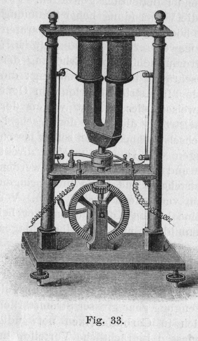
Operated by a hand crank.
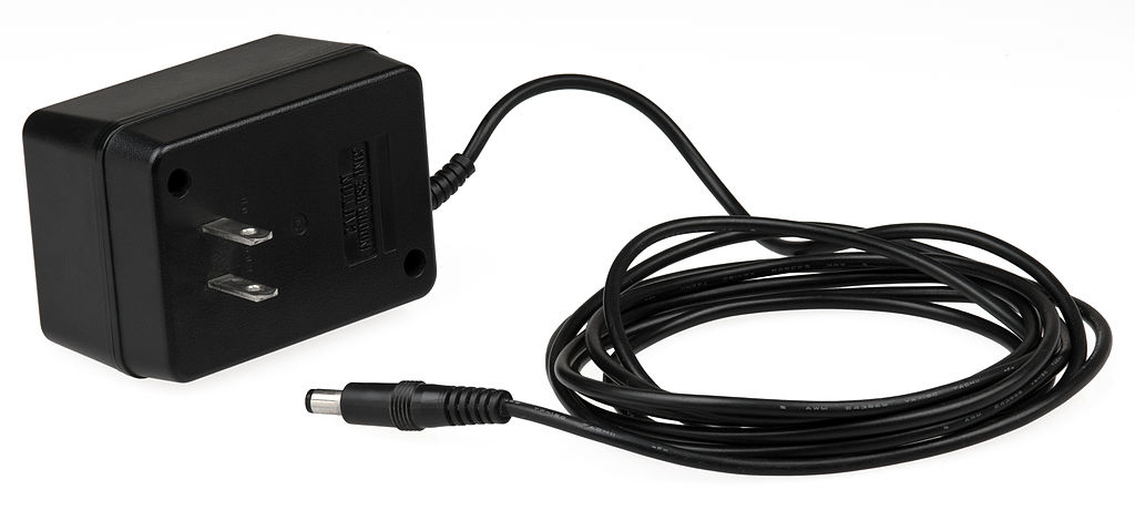
Positive center is way more popular: gearspace.com/board/electronic-music-instruments-and-electronic-music-production/1222518-center-negative-vs-center-positive-power-supply.html
This notation is designed to be relatively easy to write. This is achieved by not drawing ultra complex ASCII art boxes of every component. It would be slightly more readable if we did that, but prioritizing the writer here.
Two wires are only joined if but the following are:
+ is given. E.g. the following two wires are not joined: |
--|--
| |
--+--
|Simple symmetric components:
-,+and|: wireAC: AC source. Parameters:e.g.:Hz: frequencyV: peak voltage
If only one side is given, the other is assumed to be at a groundAC_1Hz_2VG.C: capacitorG: ground. Often used together withDC, e.g.:means applying a voltage of 10 V across a 10 Ohm resistor, which would lead to a current of 1 ADC_10---R_10---GL: inductorMICROPHONE. As a multi-letter symmetric component, you can connect the two wires anywhere, e.g.or:---MICROPHONE---| MICROPHONE |SPEAKERR: resistorSQUID: SQUID deviceX: Josephson junction
Asymmetric components have multiple letters indicating different ports. The capital letter indicates the device, and lower case letters the ports. The wires then go into the ports:
D: diodeSample usage in a circuit:a: anode (where electrons can come in from)c: cathode
Can also be used vertically like aany other circuit:--aDc--We can also change the port order, the device is still the same due to capital| a D c |D:--cDa-- | Dac-- | Dca-- | --caDDCDC source. Ports:E.g. a 10 V source with a 10 Ohm resistor would be:p: positiven: negative
If only one side is given, the other is assumed to be at a the ground+---pDC_10_n---+ | | +----R_10------+G. We can also omitpandmin that case and assume thatpis the one used, e.g. the above would be equivalent to:If the voltage is not given, it is assumed to be a variable voltage power supply.DC_10---R_10---GLED: same as diodeI: electric current source. Ports:s: electron sourced: electron destination
P: potentiometer source. Ports:1: one of the sides2: the middle3: the other side
T: transistor. The ports aresgTd:Sample usage in a circuit:s: sourceg: gated: gate
All the following are also equivalent:---+ | --sgTd--| g --sTd-- | --Tsgd-- |V: Voltmeter. Ports:If we don't need to specify explicit positive and negative sides, we can just use:p: positiven: negative
without any ports. This is notably often the case for AC circuits.---V---Optionally, we can also add the sides as in:- ports can also be separated by double underscores from the component names to increase readability. Single underscores can also be used to increase readability of longer multi-word component names e.g.:which is the same as:
RPI_PICO_W__1gp0__3gnd | | R_2k | | | +-aLEDc-+represents a circuit linking port 1 of a Raspberry Pi Pico W, which is GPIO pin 0, through a resistor and an LED, back to pin 3 of the board, which is ground.RPI_PICO_W 1gp0 3gnd | | R_2k | | | +-aLEDc-+
Numbers characterizing components are put just next to each component with an underscore. When there is only one parameter, standard units are assumed, e.g.:means:Micro is denoted as
+-----+
|     |
C_1p  R_2k
|     |
+-----+- a capacitor with 1 pico Faraday
- a resistor with 2 k Ohms
u.Wires can just freely come in and out of specs of a component, they are then just connected to the component, e.g.:means applying a voltage of 10 V across a 10 Ohm resistor, which would lead to a current of 1 A
DC_10---R_10---GIf a component has more than two parameters, units are used to distinguish them when possible, e.g.:means an AC source with:
AC_1kV_2MHz- 1 kV voltage
- 1 MHz frequency
Open Circuits book interview by CuriousMarc (2022)
Source. One more more electrical wires surrounded by an insulator.
Tagged
Main implementations: the same as electronic switches: vacuum tubes in the past, and transistors in the second half of the 20th century.
How to make an LM386 audio amplifier circuit by Afrotechmods (2017)
Source. Builds the circuit on a breadboard from minimal components, including one discrete transistor. Then plays music from phone through headset cables into a speaker.The fundamental intuition about capacitors is that they never let electrons through.
They can only absorb electrons up to a certain point, but then the pushback becomes too strong, and current stops.
Therefore, they cannot conduct direct current long term.
For alternating current however, things are different, because in alternating current, electrons are just jiggling back and forward a little bit around a center point. So you can send alternating current power across a capacitor.
The key equation that relates Voltage to electric current in the capacitor is:So if a voltage Heavyside step function is applied what happens is:More realistically, one may consider the behavior or the series RC circuit to see what happens without infinities when a capacitor is involved as in the step response of the series RC circuit.
- the capacitor fills up instantly with an infinite current
- the current then stops instantly
Finding capacitance with an oscilloscope by Jacob Watts (2020)
Source. Good experiment.Capacitors Explained by The Engineering Mindset
. Source. 2019.Pieter van Musschenbroek is the perfect example that if your surname is too complicated, things you invent will not be named after you!
Ideally can be thought of as a one-way ticket gate that only lets electrons go in one direction with zero resistance! Real devices do have imperfections however, so there is some resistance.
First they were made out of vacuum tubes, but later semiconductor diodes were invented and became much more widespread.
Diodes Explained by The Engineering Mindset (2020)
Source. Good video:- youtu.be/Fwj_d3uO5g8?t=153 how it works
- youtu.be/Fwj_d3uO5g8?t=514 applications:
- protection against accidental battery inversion
- rectifiers, notably mentions a diode bridge
The first diodes. These were apparently incredibly unreliable, especially for portable radios, as you had to randomly search for the best contact point you could find in a random polycrystalline material!!
And also quality was highly dependant on where the material was sourced from as that affected the impurities present in the material. Later this was understood to be an issue of doping.
It was so unreliable that vacuum tube diodes overtook them in many applications, even though crystal detectors are actually semiconductor diodes, which eventually won over!
For a long time, before artificial semiconductors kicked in, people just didn't know the underlying physical working principle of these detectors. What I cannot create, I do not understand basically.
This was the first generation of commercially successful radios.
It uses a crystal detector as its diode, which is a crucial element of the radio, thus its name.
They were superseded by transistor radios, which were much more reliable, portable and could amplify the signal received.
How a Crystal radio Works by RimstarOrg
. Source. GPIO generally only supports discrete outputs.
But for some types of hardware, like LEDs and some motors, the system has some inertia, and if you switch on and off fast enough, you get a result similar to having an intermediate voltage.
So with pulse width modulation we can fake analog output from digital output in a good enough manner.
Notably used to connect:
- pin headers
- breadboard holes
You can buy large sets of them in combitation of male/male, male/female, female/female. Male/male is perhaps the most important
These often come pre-soldered on devboards, e.g. and allow for easy access to GPIO pins. E.g. they're present on the Raspberry Pi 2.
Why would someone ever sell a devboard without them pre-soldered!
6x1 pin header
. Source. Underside of a Raspberry Pi 2
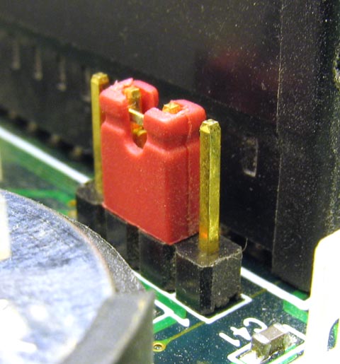
. Source. At the top of this image we can clearly see how the usually pre-soldered pin header connectors go through the PCB and are soldered on both sides.Allows you to connect two adjacent pins of a pin header. Sometimes used as a hardware configuration interface!
Something where DC voltage comes in, and a periodic voltage comes out.
- youtu.be/eYVOdlK15Og?t=66 RC oscillator on breadboard. Produces rectangular wave. Mentions popular integrated circuit that does it: 555 timer IC.
- youtu.be/eYVOdlK15Og?t=175 LC oscillators allows for higher frequencies. Produces sinusoidal output on MHz range. Uses an amplifier to feed back into input and maintain same voltage. Hard to make reliably on breadboard.
- youtu.be/eYVOdlK15Og?t=315 crystal oscillator. Mentions it acts like an LC oscillators. Shows and equivalent model. Wish he had talked more about them. You need support components around it: similarly to the LC case, the amplifier is generally not packaged in.
Oscillator made of an LC circuit.
From Raw Crystal to Crystal oscillator
. Source. by United States Army Signal Corps (1943)How LEDs work by VirtualBrain
. Source. 2021. Good 3d schematics clearly explaining part of the LED electronic package.How are LED Chips and LED Encapsulation is made by Future Linear
. Source. Starts from some level of cut square chips. Still in round wafer form.www.reddit.com/r/Optics/comments/18f6bdt/comment/kcsiook/ mentions:
LEDs are broadband by nature, since the spontaneous emission broadly speaking reflects the overlap of the Fermi distribution and the density of states
Direct and indirect band gaps is an important part of why diodes don't emit light apparently.
Bibliography:
- www.quora.com/What-is-the-difference-between-an-LED-and-a-diode
- youtu.be/9BDTtcRMxpA?t=388 from Video 11. "How LEDs work by VirtualBrain" explains the geometry aspect well
Apparently fundamentally LEDs in principle work as photodetectors, but
It resists to change in electric current. Well seen at: Video 27. "LC circuit by Eugene Khutoryansky (2016)".
Tagged
Variable resistance element.
Although transistors were revolutionary, it is fun to note that they were just "way cheaper and more reliable and smaller" versions of exactly the main functions that a vacuum tube could achieve
People had already patented a lot of stuff before without being able to make them work. Nonsense.
As the name suggests, this is not very sturdy, and was quickly replaced by bipolar junction transistor.
By William Shockley in 1948 also at Bell Labs Murray Hill.
As of 2020, not used anymore in logic gates, but still used in amplifiers.
FNIRSI 1014D review by Kerry Wong (2022)
Source. One of the cheapest oscilloscopes available at the time.DIY Oscilloscope Kit (20$) VS Regular DS Oscilloscope (400$) by Great Scott (2016)
Source. By Andy Haas, an experimental particle physics professor: as.nyu.edu/content/nyu-as/as/faculty/andy-haas.html What an awesome dude!
899 USD as of 2022, takes a year to ship as they gather up a lot of orders before producing.
Sounds so cool, especially the multi functionality. Shame so expensive.
Tagged
They do seem to have been very innovative, and have had a very good work culture. They also had a huge impact on the Silicon Valley startup scene.
Some products they are known for:
- oscilloscopes
- Atomic clocks, notably highly portable ones, see e.g. Video "Inside the HP 5061A Cesium Clock by CuriousMarc (2020)"
- pocket calculator
HP Origins promotional documentary by HP (2006)
Source. A bit too star eyed, but gives some good ideas. Tagged
In a way, Agilent represents the most grassroots electronics parts of HP from before they became overly invested in laptops and fell.
They spun out the electronics part as Keysight in 2014, becoming life science only.
This is the cutest product name ever.
Since 1992, Mr. SQUID has been the standard educational demonstration system for undergraduate physics lab courses.
YBCO device, runs on liquid nitrogen.
Tagged
This is how electronic circuits are normally prototyped!
Once you validate them like this, the next step is usually to move on to printed circuit boards for more reliable production setups.
Breadboards are a thing of beauty and wonder.
Point-to-point constructions on woden boards
. Source. Predecessors to breadboards from where the name came. A thing of beauty, so vintage. You could actually write stuff on those with a pencil! Tagged
Bluetooth support: not enough RAM for it, though in principle its chip/transceiver could support it! microbit-micropython.readthedocs.io/en/v1.0.1/ble.html
Supported editors: microbit.org/code/
MicroPython web editor and compiler: python.microbit.org/v/2
Everything in this section is tested on the Micro Bit v1 from Micro Bit v1 unless otherwise noted.
Bibliography:
Microbit simulator using some Microsoft framework.
TODO the Python code from there does not seem to run on the microbit via
uflash, because it is not MicroPython.support.microbit.org/support/solutions/articles/19000111744-makecode-python-and-micropython explains.
forum.makecode.com/t/help-understanding-local-build-options/6130 asks how to compile locally and suggests it is possible. Seems to require Yotta, so presumably compiles?
Presumably this is because Microsoft ported their MakeCode thing to the MicroBit, and the Micro Bit foundation accepted them.
E.g. there toggling a LED:but the code that works locally is a completely differently named API Microsoft going all in on adopt extend extinguish from an early age!
led.toggle(0, 0)set_pixel:microbit.display.set_pixel(0, 0, )When plugged into Ubuntu 22.04 via the USB Micro-B the Micro Bit mounts as:e.g.:for username
/media/$USER/MICROBIT//media/ciro/MICROBIT/ciro.Loading the program is done by simply copying a The file name does not matter, only the
.hex binary into the image e.g. with:cp ~/Downloads/microbit_program.hex /media/$USER/MICROBIT/.hex extension.The back power light flashes while upload is happening.
Flashing takes about 10-15 seconds for the 1.8 MB scroll display hello world from microbit-micropython.readthedocs.io/en/v1.0.1/tutorials/hello.html:and the program starts executing immediately after flash ends.
from microbit import *
display.scroll("Hello, World!")You can restart the program by clicking the reset button near the USB. When you push down the program dies, and it restarts as soon as you release the button.
Build worked:but flash failed:Related: mattoppenheim.com/2018/06/24/using-udev-to-remove-the-need-for-sudo-with-the-bbc-microbit
west build -d build/microbit/hello_world -b bbc_microbit samples/hello_worldwest flash -d build/microbit/hello_worldThe build also generates a .hex file by default, and we've tried to flash it manually with:but we failed to see it do anything with zephyr/blink_gpio.c, so not sure if the flashing was broken or if the code was broken, or if we didn't find the IO pins correctly.
cp build/microbit/hello_world/zephyr/zephyr.hex /media/ciro/MICROBIT/Bibliography:
To use a prebuilt firmware, you can just use What that does is:
uflash, tested on Ubuntu 22.04:git clone https://github.com/bbcmicrobit/micropython
cd micropython
git checkout 7fc33d13b31a915cbe90dc5d515c6337b5fa1660
uflash examples/led_dance.py- convert the MicroPython code to bytecode
- join it up with a prebuilt firmware that ships with uflash which contains the MicroPython interpreter
- flashes that
To build your own firmware see: Compile MicroPython code for Micro Bit locally on Ubuntu 22.04 with your own firmware
TODO didn't manage from source Ubuntu 22.04, their setup bitrotted way too fast... it's shameful even. Until I gave up and went for the magic Docker of + github.com/bbcmicrobit/micropython, and it bloody worked:
git clone https://github.com/bbcmicrobit/micropython
cd micropython
git checkout 7fc33d13b31a915cbe90dc5d515c6337b5fa1660
docker pull ghcr.io/carlosperate/microbit-toolchain:latest
docker run -v $(pwd):/home --rm ghcr.io/carlosperate/microbit-toolchain:latest yt target bbc-microbit-classic-gcc-nosd@https://github.com/lancaster-university/yotta-target-bbc-microbit-classic-gcc-nosd
docker run -v $(pwd):/home --rm ghcr.io/carlosperate/microbit-toolchain:latest make all

# Build one.
tools/makecombinedhex.py build/firmware.hex examples/counter.py -o build/counter.hex
cp build/counter.hex "/media/$USER/MICROBIT/"

# Build all.
for f in examples/*; do b="$(basename "$f")"; echo $b; tools/makecombinedhex.py build/firmware.hex "$f" -o "build/${b%.py}.hex"; done
The pre-Docker attempts:
sudo add-apt-repository -y ppa:team-gcc-arm-embedded
sudo apt update
sudo apt install gcc-arm-embedded
sudo apt install cmake ninja-build srecord libssl-dev

# Rust required for some Yotta component, OMG.
sudo snap install rustup
rustup default 1.64.0

python3 -m pip install yotta
The line:warns:and then the update/
sudo add-apt-repository -y ppa:team-gcc-arm-embeddedE: The repository 'https://ppa.launchpadcontent.net/team-gcc-arm-embedded/ppa/ubuntu jammy Release' does not have a Release file.
N: Updating from such a repository can't be done securely, and is therefore disabled by default.
N: See apt-secure(8) manpage for repository creation and user configuration details.sudo apt-get install gcc-arm-embedded fails, bibliography:Attempting to install Yotta:or:was failing with:Running:did not help. Bibliography:
sudo -H pip3 install yottapython3 -m pip install --user yottaException: Version mismatch: this is the 'cffi' package version 1.15.1, located in '/tmp/pip-build-env-dinhie_9/overlay/local/lib/python3.10/dist-packages/cffi/api.py'. When we import the top-level '_cffi_backend' extension module, we get version 1.15.0, located in '/usr/lib/python3/dist-packages/_cffi_backend.cpython-310-x86_64-linux-gnu.so'. The two versions should be equal; check your installation.python3 -m pip install --user cffi==1.15.1From a clean virtualenv, it appears to move further, and then fails at:So we install Rust and try again, OMG:which at the time of writing was
Building wheel for cmsis-pack-manager (pyproject.toml) ... error
error: [Errno 2] No such file or directory: 'cargo'sudo snap install rustup
rustup default stablerustc 1.64.0, and then OMG, it worked!! We have the yt command.However, it is still broken, e.g.:blows up:bibliography:
git clone https://github.com/lancaster-university/microbit-samples
cd microbit-samples
git checkout 285f9acfb54fce2381339164b6fe5c1a7ebd39d5
cp source/examples/invaders/* source
yt clean
yt buildannot import name 'soft_unicode' from 'markupsafe'Official support is abysmal, very focused on MicroPython and their graphical UI.
The setup impossible to achieve as it requires setting up the Yotta, just like the impossible to setup Compile MicroPython code for Micro Bit locally on Ubuntu 22.04 with your own firmware setup.
So we just use github.com/lancaster-university/microbit-samples + github.com/carlosperate/docker-microbit-toolchain:.hex file size for the hello world was 447 kB, much better than the MicroPython hello world downloaded from the website which was about 1.8 MB!
docker pull ghcr.io/carlosperate/microbit-toolchain:latest
git clone https://github.com/lancaster-university/microbit-samples
cd microbit-samples
git checkout 285f9acfb54fce2381339164b6fe5c1a7ebd39d5

# Select a sample, builds one at a time. The default one is the hello world.
cp source/examples/hello-world/* source

# Build and flash.
docker run -v $(pwd):/home --rm ghcr.io/carlosperate/microbit-toolchain:latest yotta build
cp build/bbc-microbit-classic-gcc/source/microbit-samples-combined.hex "/media/$USER/MICROBIT/"If you try it again for a second time from a clean tree, it fails with:presumably because after Yotta died it started using GitHub as a registry... sad. When will people learn. Apparently we were at 5000 API calls per hour. But if you don't clean the tree, you will be just fine.
warning: github rate limit for anonymous requests exceeded: you must log inIdentification: kitronik.co.uk/blogs/resources/explore-micro-bit-v1-microbit-v2-differences The easiest thing is perhaps the GPIO notches.
- microbit/micropython/uart.py: the Micro BIt comes with a UART simulator via the USB connection, it is very convenient: support.microbit.org/support/solutions/articles/19000022103-outputing-serial-data-from-the-micro-bit-to-a-computer To output data to the computer simply use Python
print. To receive you can e.g. use GNU screen:It appears to be very unreliable however, some times it shows up, sometimes it doesn't.screen /dev/ttyACM0 115200
Pinout overview: makecode.microbit.org/device/pins Basically 0, 1, and 2 are the truly generic ones. They can also serve as ADCs.
Micropython documentation: microbit-micropython.readthedocs.io/en/latest/pin.html
In the 2010's/2020's, many people got excited about getting children in to electronics with cheap devboards, notably with Raspberry Pi and Arduino.
While there is some potential in that, Ciro Santilli always felt that this is very difficult to do, while also keeping his sacred principle of backward design in mind.
The reason for this is that "everyone" already has much more powerful computers at hand: their laptops/desktops and even mobile phones as of the 2020s. Except perhaps if you are thing specifically about poor countries.
Therefore, the advantage using such devboards for doing something that could useful must come from either:
- their low cost. This would be an important consideration if you were to mass produce your product, but that is not going to be the case for learners, at least initially.
- their portability, and closely linked their ability to act as sensors
- their ability to act as actuators, which is often missing from regular computers
- them having hardware accelerators that are not normally present in regular computers, e.g. FPGAs or AI accelerators. And then the demo project must demonstrate that the project is able to do something significantly faster/cheaper on the devboard than on a desktop computer.
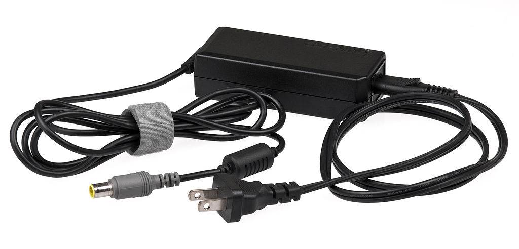
Many devborads require a 5V power supply.
For battery power you need a transformer.
Many/most microcontroller boards have analog-to-digital converters built into them, it is very convenient. E.g. it is the case for the Raspberry Pi Pico.
Open Source 8.5 Digit Voltmeter from CERN by Marco Reps (2021)
Source. When Ciro Santilli was studying electronics at the University of São Paulo, the courses, which were heavily inspired from the USA 50's were obsessed by this one! Thinking about it, it is kind of a cool thing though.
That Wikipedia page is the epitome of Wikipedia failure to explain things in a way that is of any interest to any learner. Video 24. "Tutorial on LC resonant circuits by w2aew (2012)" is the opposite.
Tutorial on LC resonant circuits by w2aew (2012)
Source. - youtu.be/hqhV50852jA?t=239 series LC circuit on a breadboard driven by an AC source. Shows behaviour on oscilloscope as source frequency is modified. We clearly see voltage going to zero at resonance. This is why thie circuit can be seen as a filter.
- youtu.be/hqhV50852jA?t=489 shows the parallel LC circuit. We clearly see current reaching a maximum on resonance.
LC circuit dampened oscillations on an oscilloscope by Queuerious Guy (2014)
Source. Finally a video that shows the oscillations without a driving AC source. The dude just move wires around on his breadboard manually, first charging the capacitor and then closing the LC circuit, and is able to see damped oscillations on the oscilloscope.Introduction to LC Oscillators by USAF (1974)
Source. - youtu.be/W31CCN_ZF34?t=740 mentions that LC circuit formation is the root cause for Audio feedback with a quick demo. Not very scientific, but cool.
LC circuit by Eugene Khutoryansky (2016)
Source. Exactly what you would expect from an Eugene Khutoryansky video. The key insight is that the inductor resists to changes in current. So when current is zero, it slows down the current. And when current is high, it tries to keep it going, which recharges the other side of the capacitor.Both are harmonic oscillators.
In the LC circuit:
- the current current may be seen as the velocity and containing the kinetic energy
- the charge stored in the capacitor as the potential energy
You can kickstart motion in either of those systems in two ways:
- charge the capacitor, i.e. pull the string, and then let it go, i.e. close the circuit. This is the simpler one to realise. Shown concretely at: Video 25. "LC circuit dampened oscillations on an oscilloscope by Queuerious Guy (2014)"
- give speed to the mass, i.e. make a current pass through the inductor
He participated in the development of the electrical telegraph, and he did some good modeling work that improved the foundations of the field, notably creating the telegrapher's equations.
He was one of those idealists who just want to do some cool work even if they have to starve for it, people had to get a state pension for him for his contributions. Nice guy. en.wikipedia.org/w/index.php?title=Oliver_Heaviside&oldid=1230097796#Later_years_and_views:He also never married: www.nndb.com/people/627/000204015/
In 1896, FitzGerald and John Perry obtained a civil list pension of £120 per year for Heaviside, who was now living in Devon, and persuaded him to accept it, after he had rejected other charitable offers from the Royal Society.
Oliver Heaviside c. 1900
. Source. Mostly on vintage electronics. Lots of focus on microwave, which he has worked a lot with.
Has been going wild with restoration and reverse engineering of the Apollo moon mission.
Inside the WILD Lab of CuriousMarc by Keysight Labs (2022)
Source. - youtu.be/qwocVH3_1Eo?t=841 the IBM System/360 is insane!
Marc Verdiell is a French electrical engineer born in 1963 or 1964[ref] and best known for being the creator and host of the CuriousMarc YouTube channel where he does mind blowing repairs and reverse engineering of vintage computers and other electronic equipment.
Marc sold his company LightLogic, an optoelectronics company he founded, to Intel in April 2001. This was just after the dot-com crash, but Intel apparently still correctly believed that the networking and the Internet would continue to grow and was investing in the area. His associate Frank Shum sued claiming he should be credited for some of the inventions sold but lost and Marc got it all.[ref][ref][ref]. Marc was then almost immediately appointed an Intel fellow at the extremelly early age of 37, and then stayed for a few years at Intel until 2006 according to his LinkedIn.[ref][ref]
Marc's LinkedIn profile: www.linkedin.com/in/marc-verdiell-9742795/
Marc's full name is actualy Jean-Marc Verdiell, but Ciro Santilli remembers there was one YouTube video where he mentions he gave up on "Jean" partly because anglophones would murder its pronounciation all the time.
Marc's PhD thesis is listed at: theses.fr/1990PA112048 and it is entitled:which is translated into English as:but the full text is not available online.
Mise en phase de reseaux de lasers a semi-conducteur
Phase locking of semiconductor laser arrays
Profile of Marc Verdiell by Gizmodo (2018)
Source. youtu.be/ZgAreiFXhJk?t=253 lists some famous people who live there. It's like a micro heaven.
And a person who makes open educational content like Marc, truly deserves it.
Atherton managed to keep the entire place green and every house has a pool. Wikipedia comments web.archive.org/web/20220906010554/https://www.forbes.com/home-improvement/features/most-expensive-zip-codes-us/:
Atherton is known for its wealth; in 1990 and 2019, Atherton was ranked as having the highest per capita income among U.S. towns with a population between 2,500 and 9,999, and it is regularly ranked as the most expensive ZIP Code in the United States [(94027)]. The town has very restricting zoning, only permitting one single-family home per acre and no sidewalks. The inhabitants have strongly opposed proposals to permit more housing construction and Forbes confirms it for 2022: web.archive.org/web/20220906010554/https://www.forbes.com/home-improvement/features/most-expensive-zip-codes-us/, by far on top.
Marc has reached out to us and requested that some personal information be removed from this article, to which we complied.
Company founded by Marc Verdiell in his garage, and later acquired by Intel which was going on a optoelectronics buying spree. The division was later sold off in 2023 of course during more difficult times: www.theregister.com/2023/10/31/intel_silicon_photonics_jabil/
It's hard to understand exactly what the company did by Googling it nowadays. Sad and usual fate. Presumably something related to transceiver for fiber-optic communication. Only the patents remain: patents.google.com/?assignee=lightlogic&oq=lightlogic to tell its story to the brave.
This mostly faceless German dude is awesome!
 Ciro Santilli
 OurBigBook.com